Without modifying the firmware image.
A firmware reverse-engineering journey from a missing memory channel to a small, bootable UEFI utility.
My home lab server (a Fujitsu PRIMERGY TX2550 M5) offers more BIOS configuration options than its normal setup interface reveals. Behind the standard menus sits an internal Admin menu containing additional CPU, memory, and platform settings.
My fujitsu-admin-menu-unlock repository provides a small UEFI application that exposes this menu on the tested system. It does not patch a BIOS image or flash modified firmware. Instead, it changes one carefully identified, volatile UEFI variable.
In this article, you’ll read how I identified the UEFI variable. Why the firmware shortcut key didn’t work. And how I packaged the app into a bootable ISO.
WARNING: Unofficial tool! Tested on Fujitsu PRIMERGY TX2550 M5 with D3386-B1 mainboard and BIOS V5.0.0.14 R1.44.0 (September 30, 2025). No other platform or firmware version tested. Unlocking the internal settings does not mean the internal settings are safe or supported.
Tools used:
- GitHub Copilot
- REA with Ghidra
- MinGW-w64 GCC
- Fujitsu iRMC S5
- Python, PowerShell etc.
Part 1: A memory problem
The investigation began with a server reporting only 48 GB of usable memory despite having four 16 GB DDR4 modules installed.
Swapping modules did not move the problem away from the affected memory path. The normal BIOS interface provided limited diagnostic information, so the next question was straightforward:
Did the firmware contain additional memory diagnostics that the standard setup interface was hiding?
Rather than relying on generic “secret BIOS key” suggestions, I examined the firmware version actually installed on the server.
The analysis used the original 16 MiB D3386-B1.ROM from Fujitsu’s update package. Its SHA-256 was recorded to keep subsequent findings tied to that exact image:
faeb39b6f76d3efab498e69880084f593b5a06228187b8044e22cba2ac912f64The original image remained unchanged.
Part 2: Looking inside the BIOS
An UEFI firmware image is a container of firmware volumes, files, compressed sections, executable modules, and configuration data; not simply one executable.
I used Python’s uefi_firmware package to traverse the image and extract relevant executable sections. Custom Python scripts then decoded the firmware’s HII strings and IFR forms.
HII, the Human Interface Infrastructure, supplies much of the text and structure used by UEFI setup interfaces. IFR, the Internal Forms Representation, describes questions, options, navigation links, and conditions such as “hide this item when this expression is true.”
That distinction matters: finding the string “Admin” would only establish that the text exists. Following the form definitions established where the menu belonged and what controlled its visibility.
The decoded configuration revealed this navigation path:
Advanced
└── Admin
    └── Socket Configuration
        └── Memory Configuration
It also exposed internal options for memory testing, training behavior, and diagnostic reporting.
The Admin menu was not missing from the firmware. Its entry was being suppressed.
Part 3: The visibility flag
Following the IFR references led to a UEFI variable:
Name:       FjSetupHiddenAdminPage
GUID:       77d054d6-53c6-4215-b9c3-66637fcab7ce
Size:       1 byte
Attributes: 0x02
Ok, this sounds promising.
A value of 1 hides the entry. A value of 0 removes that particular suppression condition.
The GUID is a firmware-defined namespace identifier.
I also identified a firmware driver named FjHiddenAdminPage. Its code initializes the variable to 1, using attributes 0x02.
That attribute value was central to the eventual approach.
In UEFI, 0x02 means EFI_VARIABLE_BOOTSERVICE_ACCESS. It does not include the EFI_VARIABLE_NON_VOLATILE attribute. This is a volatile, boot-services-accessible variable;not a persistent setup value that our application needs to store in flash.
It also lacks runtime access, which is why a pre-OS UEFI application was appropriate rather than a normal operating-system utility.
Part 4: Why Alt+A did not work
Native code analysis revealed that the AMI setup application, AMITSE, registers an Alt+A handler.
At first glance, that looked like the intended entry method, which I immediately tried. The handler toggles the hidden-admin variable; but only after another condition passes.
The code first checks a platform predicate backed by a Fujitsu GPIO read protocol. If that predicate does not permit the operation, the hotkey does not reach the variable toggle.
This explained why identifying the shortcut statically was not enough. Repeated attempts through the iRMC console (= too lazy to connect a monitor and keyboard) did not expose the menu.
To distinguish a blocked firmware path from a keyboard-delivery problem, I built a separate read-only UEFI diagnostic.
It read the visibility variable and called the existing Fujitsu GPIO protocol’s read callback. On the actual server, it reported:
Hidden Admin value: 1
Raw GPIO input:     1
Admin gate (raw^1):  0
The runtime result matched the code: the gate blocked the hotkey path.
I did not change the GPIO or move a motherboard jumper (see previous explanation why). Although the maintenance documentation identifies security-related jumpers, their exact electrical relationship to this gate was not established.
The useful finding was narrower: the menu’s visibility flag could be addressed independently of the gated hotkey.
Part 5: Turning the finding into an UEFI application
The final application does not implement a general-purpose firmware-variable editor. Its scope is deliberately restricted to just one operation.
The logic in admin-menu-unlock.c is:
Read the exact variable by name and GUID.

If the read fails:
    Stop without writing.

Require:
    Size == 1
    Attributes == 0x02
    Value is either 0 or 1

If the value is already 0:
    Report that no write is necessary.

Otherwise:
    Attempt one write: 01 -> 00.
    Preserve attributes 0x02.
    Read the variable back.
    Require size 1, attributes 0x02, and value 0.
Unexpected attributes are grounds for refusal. For example, the application will not accept a variable that has become nonvolatile.
There are no automatic retries, GPIO writes, disk writes, firmware-image patches, or resets.
Booting the ISO automatically runs this guarded operation. It is not a read-only viewer and does not ask for confirmation before the single permitted write attempt.
Afterward, the application stays on its status screen until Escape is pressed.
Part 6: Compiling a UEFI executable without EDK II
The implementation uses a small set of C definitions for the UEFI structures and service functions it needs. It does not require EDK II or proprietary Fujitsu headers.
Compile-time assertions check important structure offsets, including the locations of GetVariable and SetVariable.
The x64 MinGW-w64 compiler produces a PE executable with the EFI Application subsystem and efi_main as its entry point. The essential build command is:
x86_64-w64-mingw32-gcc `
    -std=c11 -O2 -Wall -Wextra -Werror `
    -ffreestanding -fshort-wchar -mno-red-zone -fno-stack-protector `
    -fno-asynchronous-unwind-tables -fno-unwind-tables `
    -ffunction-sections -fdata-sections -nostdlib `
    "-Wl,--subsystem,10" "-Wl,--entry,efi_main" `
    "-Wl,--image-base,0x10000000" "-Wl,--gc-sections" `
    -o .\build\admin-menu-unlock.efi .\admin-menu-unlock.c
Notable choices include -fshort-wchar for UEFI-compatible 16-bit wide characters, -mno-red-zone for firmware execution, and -nostdlib to avoid depending on a normal operating-system runtime.
The resulting application calls services supplied by the firmware.
Part 7: From an EFI file to a bootable ISO
An .efi executable is not, by itself, a bootable virtual CD.
The repository’s build-iso.py packages it in two layers:
admin-menu-unlock.iso
├── El Torito UEFI boot entry
├── EFIBOOT.IMG
│   └── EFI
│       └── BOOT
│           └── BOOTX64.EFI
└── ADMIN.EFI
First, pyfatfs creates a 1.44 MiB FAT12 image. The application is placed at the standard x64 fallback boot path:
\EFI\BOOT\BOOTX64.EFINext, pycdlib embeds that image into an ISO and creates an El Torito boot entry with platform ID 0xEF, identifying it as a UEFI boot image.
The ISO also contains a separate copy of the executable as ADMIN.EFI.
The released unlock image boots the application directly. It does not need a UEFI shell or a startup script.
Before packaging, the builder checks the executable’s PE signature, x64 machine type, EFI application subsystem, and absence of actual Windows DLL imports. After packaging, it reads the contents back from both the FAT image and the ISO and compares them with the inputs. It also prints artifact sizes and SHA-256 hashes.
These checks establish packaging integrity; not hardware compatibility.
Part 8: What happened on the server
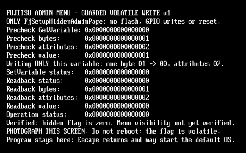
The read-only diagnostic successfully ran through iRMC controller-side NFS virtual media.
The unlock utility was subsequently booted on first try.
The decisive confirmation came afterward: entering Setup without resetting the server exposed the Admin menu.
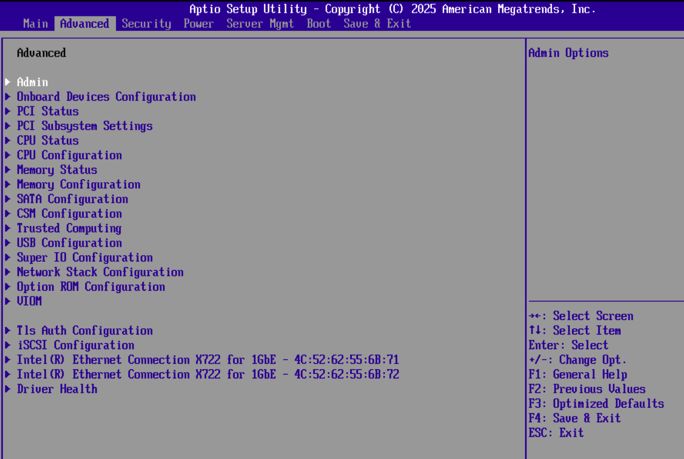
That same-boot transition matters. Resetting loses the volatile state; firmware initialization can hide the menu again.
The newly accessible Memory Topology view then provided information absent from the normal interface: the affected DIMM was present but disabled, while the other three modules were enabled.
The utility had unlocked access to diagnostics. It had not repaired the memory problem.
Part 9: Temporary access does not make every setting temporary
The visibility change is volatile, but that does not mean everything done inside the newly exposed menu is temporary.
Saving other BIOS settings may persist those settings normally. Internal options may also be unsuitable for a particular CPU, memory configuration, or production workload. In other word: The Admin menu is a perfect candidate to brick or destroy your hardware.
The application checks the variable’s identity, size, attributes, and value. It does not check the server model or BIOS version. Passing its guards is therefore not a compatibility guarantee.
The central result is specific: on the tested TX2550 M5 firmware, an existing Admin menu is hidden by a one-byte volatile variable. Understanding that mechanism made it possible to expose the menu with a small, inspectable UEFI application; without modifying or reflashing the BIOS image.
Part 10: Some screenshots
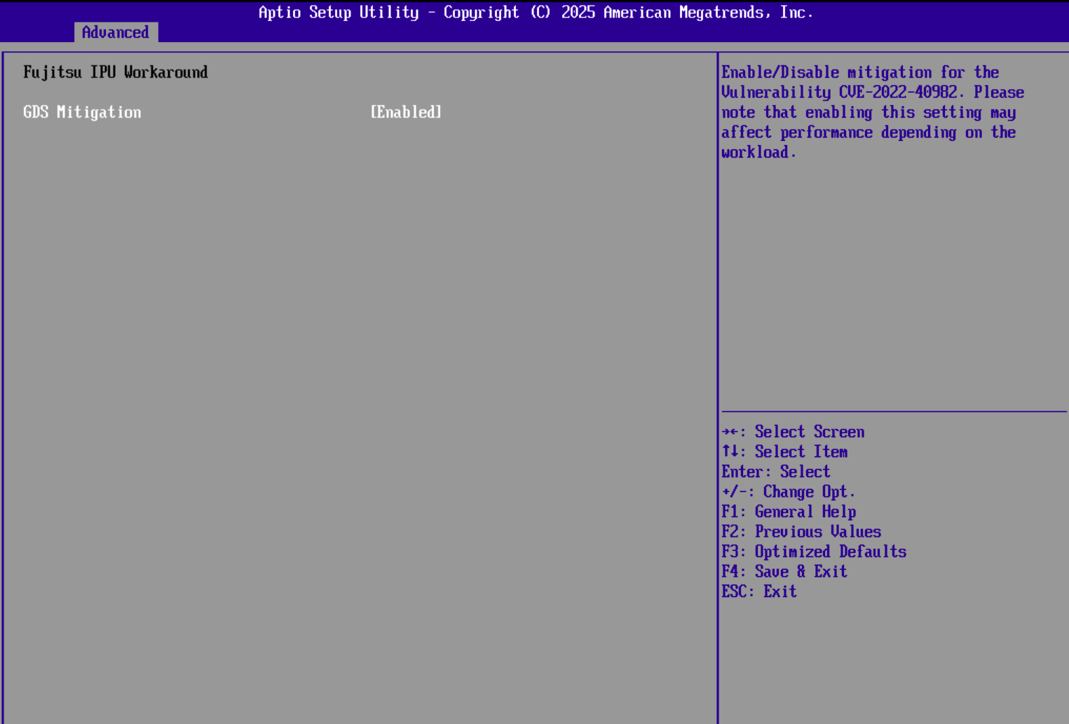
Intel’s workaround from CVE-2022-40982 (“Downfall”) can be deactivated from the Admin menu, which is something you might consider when running heavy computations in your home lab.
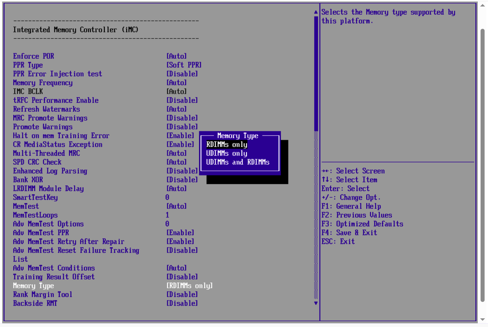
From the integrated memory menu it’s possible to enable UDIMM support. To my knowledge, it’s not possible to mix both RDIMM and UDIMM. You might need to use either one or the other.
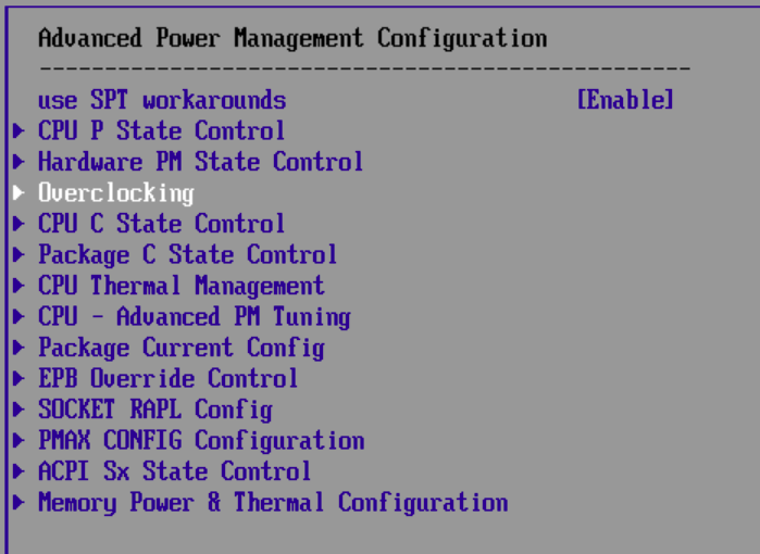
The Admin menu offers plenty of possibilities to fine-tune the power consumption of the system. One option is to underclock cores.
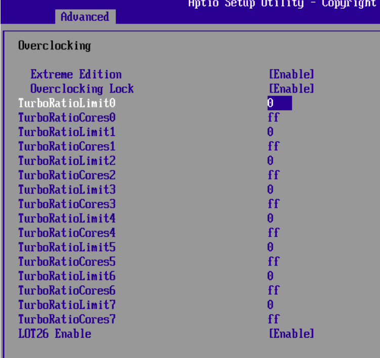
… or the exact opposite.